Showing posts with label cad tips. Show all posts

6.28.2017

My 5 Timesaver Tips for a CAD Techie

My 5 Timesaver Tips for a CAD Techie

1. When you want to suppress the display of the boundary of a layout viewport, you should turn off the layer of the non-rectangular viewport instead of freeze it.  If the layer of a non-rectangular layout viewport is frozen. the viewport is not clipped correctly. AFTER USING "LAYFRZ" COMMAND, VIEWPORT RETURN TO RECTANGULAR SHAPE.

layfrz


2. How to recover deleted file:
Folder -> Right Click then Properties -> previous Tab -> Select version of the folder that contains the file before it was deleted -> view -> View the folder and select the file that will be recovered -> Drag and drop, or cut and paste, the shadow copy to the desktop or folder on the end user’s local machine.
dwg-prop


3. Can’t Purge $AUDIT-BAD-LAYER
Sometimes after you run the AUDIT command, you will see a layer in the Layer Manager called “$AUDIT-BAD-LAYER,” and even though you PURGE the layer, it seems to keep showing up.

Here’s how to get rid of it permanently:
3.1. Run the AUDIT command.
3.2. Run the PURGE command to get rid of the layer.
3.3. Now SAVE your drawing and exit out of it.
3.4. Reopen your drawing, and when you run the PURGE command, the bad layer will be gone
Source: AUGIWorld FEB 2017 Issue

4. e-TRANSMIT
ETRANSMIT command pulls together all files that the main DWG file depends on.  What if files are too many and you keep adding the file one by one?
See image below. Open the current folder you are working on. Select the files are ready for e-transmit. Then do DRAG AND DROP magic.

e-transmit


5.  Guide on how to change Xref filename which is already attached/overlay to a drawing without detaching and reattaching again.

4.23.2015

Layer Tips and Create Tables Linking To an Excel Spreadsheet

Layer Tips and Create Tables Linking To an Excel Spreadsheet

You can create a printable layer list from the new layer palette by selecting everything (CTRL+A), copying (CTRL+C) and then opening a new spreadsheet and pasting (CTRL+V).

layer-manager

Next tip: After pasting the data to spreadsheet. One easy way to do this is to copy the data from Excel. Select all of these items and then copy them to the Windows clipboard. Make sure the spreadsheet file is saved.  See Image 01 below.

spreadsheet
Image 01

Next, go back to AutoCAD. Then, in AutoCAD in the Clipboard panel on the Home ribbon tab, I'll select Paste Special. AutoCAD displays the Paste Special dialog. See image 02 below.
ribbon-tab
Image 02

In this dialog, I'll select Paste Link to paste the contents of the clipboard as a link. Notice that when I select Paste Link, I have a choice of pasting as a Microsoft Excel Worksheet or as AutoCAD Entities. Choose AutoCAD entities then Ok. See image 03 below.

paste-special-dialog-box
Image 03
As you hover the table there has an image look like a chain and padlock, these properties of the table have been linked and locked. To do this, click the cell; look up in the ribbon tab under “Table Cell” find the Cell Locking tab.  You will find the option of this, choose “Unlocked” and now you’re ready for editing.


autocad-table


Thanks for reading. Have a thoughts to share? Any comments are appreciated here. Next tutorial tips more on AutoCAD table editing and modifying.

9.01.2013

CAD Tip Of The Day: How to reconcile layers

How to reconcile layers

In this tutorial, we will see a simple step to just How to reconcile layers. Although it has nothing to do but sometimes we ignore this. Likewise our drawing has too many layers especially if we have Xref or external reference drawings. We still purge and audit, and it still appears in the lower right corner in your AutoCAD screen. See image below the yellow triangle with an exclamation point.

reconcile-layer-in-AutoCAD

Here is the flow:
1. Type” LA” without the quotes in your command line, under the layer properties manager, choose unreconciled new layers; in the middle column choose any layer with blue color highlight.

2. Then Ctrl+A, right click and choose reconcile layer.

layer-state-manager

You will notice, the Unreconciled layers are compressed and under filter column all went to All Used Layers.

8.21.2013

A Very Quick Tip- Aligned with Dimension Line

Problem: Using “dimalign” command but text is not align with the dimension line when you stretch to left or right. See the image below.
AutoCAD-dimension

But you wanted to align the text with the dimension line. See the image below.
AutoCAD-dimension

Solution: Type” D” (without the quotes) for Dimension Style Manager, clicks Modify and chooses the Text tab. In-text alignment, choose Aligned with dimension line. That’s it. See image below.

dimension-manager-tab


Does it make sense? Anyone can share your ever secret tips. Be a guest blogger for AutoCAD.


8.11.2013

CAD Tip Of The Day: How to isolate objects and hide it.

How to isolate objects and hide it.

1. Type the "isolateobjects" in the command line (without the quotes). Select the objects you want to isolate. 
2. Another options select first the object you want to isolate. Right-click in the drawing area and select Isolate Objects. Only the selected objects are displayed. All other objects are hidden.
3. To redisplay hidden objects, right-click in the drawing area and select Isolate End Object Isolation.

Its same process with hide object

4. Select the objects you want to hide. 
5. Right-click in the drawing area and select Isolate Hide Objects. 
6. The selected objects are hidden. (It’s like the command action of layoff)
7. To redisplay hidden objects, right-click in the drawing area and select Isolate End Object Isolation. 
isolate-object-in-autocad

Try to save, close, and reopen your drawing, the object is still there the time you isolate or hide. 
TIP: Before hiding or isolating objects, set OBJECTISOLATIONMODE to 1.

6.21.2013

CAD Tip Of The Day :Multifunctional Grips in AutoCAD

Dimensioning with Grips
Using AutoCAD 2012 you can now define baseline, continuous dimension, stretch and flip arrow. Without typing the command in command line but instead using the grips of the dimension and you can choose with variable options. More on that even the text dimension you can manipulate how will look like to your settings. However only dimension break is not on the list. Thanks to the power of Multifunctional Grips.


Multifunctional grips
You can do several more things with grips. Since AutoCAD 2011, Autodesk has introduced multifunctional grips. This was later enhanced in AutoCAD 2012. With multifunctional grips, you can choose what modification you would like to perform. You need only select an object, and then move your cursor above a grip. Grips not only allow you to use fewer tools, they also provide quicker and easier methods.
Previously, it was not easy to add a vertex to a complex polyline. Multifunctional grips now allow you to click a grip and quickly add vertex on that location.

Take a quick look below the image and you can try this at home
multifunctional-grips
the cross-hair is hovering to the grips of text dimension


multifunctional-grips
the cross-hair is hovering to the grips at the extension line of dimension

Are you looking for a super-speedy way to add or modify dimensions? Multifunctional grips to the rescue! In this video tip from Cadalyst and Lynn Allen, you'll learn how multifunctional grips relate to dimensions, and get on the road to instant productivity.
Check this video.

6.12.2013

Tips Before Recovering a Drawing

Autodesk Product Support strongly recommends that you perform the following steps before recovering a corrupted drawing:

• Make a copy or copies of your drawing on reliable storage media. For example, if you suspect that your hard disk contains bad sectors, copy your files to another network drive, USB flash drive, and external hard drives. It is best to perform recovery operations on a copy of the file, since there are several different methods of recovery and each method alters the file in a different way. 
For each recovery method, it is best to use a copy of the original file since recovery processes may alter a damaged drawing yet still not recover it enough that AutoCAD can open it. 
If you retain a copy of the original damaged file, you can then use another recovery process on the original file.

• Identify and make backup copies of BAK files associated with the damaged drawing. If you open and save a damaged file without fully recovering it, you may overwrite a good BAK file with a corrupted BAK file.

• Note that there is a mechanism in AutoCAD that prevents a good BAK file from being over-written by a corrupted BAK file. When AutoCAD saves a drawing, it also checks the file for corruption. If the file is corrupted, AutoCAD does not overwrite the existing BAK file. Instead, it creates backup files that have the file extension(s). bk1, .bk2, .bk3, etc. Be aware that this process is not always successful; therefore, it is a good idea to make archive copies of good BAK files if you suspect that you have corrupted file.

• Try to identify the source of the corruption. For example, if you suspect that drawings are becoming corrupted by copying files onto a hard disk with bad sectors,you should identify and correct the problem with the hard disk before you begin to recover your files. By doing some investigation, you may find that there is more than one source that is causing the corruption or that your original assumption about what is causing the problem is incorrect.

• Record any error messages generated by AutoCAD or the operating system. Note when the messages occur in order to find a connection between the messages and when the drawing becomes corrupted. Continue to record any errors or messages that are generated during the recovery process.

Next to read:


5.05.2013

Arithmetic in AutoCAD Commands

ADDSELECTED

Differs from COPY by duplicating only the general properties of an object. For example, creating an object based on a selected circle adopts the general properties of the circle, such as its color and layer, but prompts you for the new circle’s center point and radius.
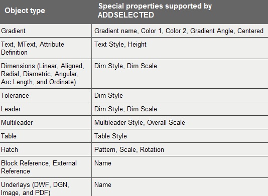
With the ADDSELECTED command, you can create a new object with the same object type as a selected object. Certain objects have special properties that are supported in addition to its general properties, as shown in the following table.


addselected


SUBTRACT
With SUBTRACT, you can create a 3D solid by subtracting one set of existing 3D solids from another, overlapping set. You can create a 2D region object by subtracting one set of existing region objects from another, overlapping set. You can select only regions for use with this command.

Note: Using SUBTRACT with 3D surfaces is not recommended. Use the SURFTRIM command instead.
Select the objects that you want to keep, press Enter, then select the objects that you want to subtract.
autocad-subtract

Objects in the second selection set are subtracted from objects in the first selection set. A single new 3D solid, surface, or region is created.


You can only subtract regions from other regions that are on the same plane. However, you can perform simultaneous SUBTRACT actions by selecting sets of regions on different planes. The program then produces separate subtracted regions on each plane. Regions for which there are no other selected coplanar regions are rejected.
You cannot use SUBTRACT with mesh objects. However, if you select a mesh object, you will be prompted to convert it to a 3D solid or surface.

DIVIDE
Creates evenly spaced point objects or blocks along the length or perimeter of an object.
The following prompts are displayed.
Select object to divide: Use an object selection method
Enter number of segments or [Block]: Enter a value from 2 through 32,767, or enter b
autocad-divide

Use DDPTYPE to set the style and size of all point objects in a drawing.

MULTIPLE
The command that you enter is repeated until you press Esc. Because MULTIPLE repeats only the command name, any parameters must be specified each time.
MULTIPLE does not repeat commands that display dialog boxes.
Note: You cannot use MULTIPLE as an argument to the AutoLISP® command function.
Multiple LINE
Step 1: Key in MULTIPLE
Step 2: Key in LINE for the commands to repeat
Step 3: Draw Several Lines without stopping the command


4.20.2013

20 Ideas for Speeding Up AutoCAD


1. Is the slowdown in all files or just one? Start a new drawing by typing .new and see if the resulting file is ok or not. If ok then the existing file is the problem. Run Recover on that file to see if that helps, see other tips further down.

2. Once a slow drawing up checks to see what fonts are being used or called. If you don't have one on your system substitute in STYLE for an AutoCAD shx font. Do this for other font names you don't recognize to see if the bits of help speed up the drawing. Change all TTF fonts to SHX to see what difference it might make.

3. Does the drawing contain XREF files? Close the current drawing, open each XREF file and audit and purge each one. Then go back to your drawing. In 2010 you can use the RECOVERALL command to also include XREFs.

4. Check-in layer manager to make sure you don't have 100's of layer filters if so delete them.

5. Check the scale list to make sure you don't have 100's of scale lists. 2009 and higher does this for you automatically, 2008 use scalelistedit, reset. Use Scale List Cleanup Utility

6. Change ALL text styles to use simplex.shx font as a test, but jot down what font is used with each style. Try QTEXT on as well to test speed. If one of these helps then you have narrowed down the problem to a text font. Add them back one at a time to find the trouble one.

7. Don't use true type fonts (TTF) and see if that helps, lots of those will slow things down. If using TTF, turn hardware acceleration off.

8. Set Shademode to 2D, do this in each layout, each viewport, and in Model Space.

9. Use -purge, Regapps, purge all. In 2010 and higher also use –purge, z (zero length geometry), and –purge, e (empty text object), -purge, g (groups).

10. Go to File>Open>History, are there hundreds or thousands of files listed? Delete most of those shortcuts keeping only the last 20 or so.

11. Properties will cause slower operating speed and some have recommended setting qpmode to 0(off). Run with Properties turned off as well as QProperties off as a test.

12. Options> Open and Save > Turn off display digital signature information.

13. Dock the command line in the lower or upper portion of the AutoCAD screen, do not have it floating. If the command line is not showing it can still have an impact if it was floating prior to being made invisible. Hit Ctrl+9 to bring it back, if it is floating then dock it at the bottom of the AutoCAD screen, then hit Ctrl+9 again.

14. Set ltscale to the proper value, a large drawing with linetypes will slow down when in MS with ltscale set to 1 or a small value.

15. Go to autodesk.com web site, pick Services and Support, use the Knowledge Base and search on "slow", "delay", etc.

16. Use Cleanscreen (CTRL+0 toggles it off and on) to remove all palettes, etc. and see if it makes a difference.


18. Turn transparency off on tool palettes. Hover over a palette and right-click, pick transparency,...

19. If you don't need draw order then set draworderctl to 0.

20. Turn DYNamic input off as a test, see DYN toggle at the bottom centre of the screen.

3.25.2013

The Triple "R" IN AutoCAD: REPAIR, RESTORE and RECOVER

Repair a Damaged Drawing File
If a drawing file is damaged, you can recover some or all of the data by using commands to find and correct errors.
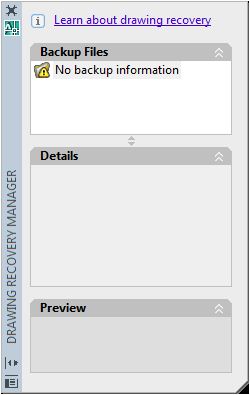
drawing-recovery

Repair and Recovery

When an error occurs, diagnostic information is recorded in the acad.err file, which you can use to report a problem.

A drawing file is marked as damaged if corrupted data is detected, or if you request that the drawing be saved after a program failure. If the damage is minor, sometimes you can repair the drawing simply by opening it. A recovery notification is displayed while opening drawing files that are damaged and need recovery. You can
  •  RECOVER. Performs an audit on, and attempts to open, any drawing file.
  •  RECOVERALL. Similar to recover, it additionally operates on all nested xrefs. The results are displayed in the Drawing Recovery Log window.
  • AUDIT. Finds and corrects errors in the current drawing.
  • RECOVERAUTO. Controls the display of recovery notifications before or after opening a damaged drawing file.

Create and Restore Backup Files
Backup files help ensure the safety of your drawing data. If a problem occurs, you can restore a drawing backup file.

Computer hardware problems, power failures or surges, user mistakes, or software problems can cause errors in a drawing. By saving your work frequently, you can ensure a minimum of lost data if your system fails for any reason. If a problem occurs, you can restore a drawing backup file.

Use Backup Files

In the Open and Save tab (Options dialog box), you can specify that backup files are created when you save drawings. If you do, each time you save a drawing, the previous version of your drawing is saved to a file with the same name and a .bak file extension. The backup file is located in the same folder as the drawing file.

You can revert to your backup version by renaming the .bak file in Windows Explorer to a file with a .dwg extension. You may want to copy it to a different folder to avoid overwriting your original file.

Save Your Drawing Automatically at Specified Intervals

If you turn the automatic save option on, your drawing is saved at specified time intervals. By default, files saved automatically are temporarily assigned the name filename_a_b_nnnn.sv$.


  • Filename is the current drawing name.
  • a is the number of open instances of the same drawing file in the same work session.
  • b is the number of open instances of the same drawing in different work sessions.
  • nnnn is a random number.

These temporary files are automatically deleted when a drawing closes normally. In the event of a program failure or a power failure, these files are not deleted.

To recover a previous version of your drawing from the automatically saved file, rename the file using a .dwg extension in place of the .sv$ extension before you close the program.

Recover from a System Failure
A hardware problem, power failure, or software problem can cause this program to terminate unexpectedly. If this happens, you can restore the drawing files that were open.

If the program fails, you can save your current work to a different file. This file uses the format, DrawingFileName_recover.dwg, where DrawingFileName is the file name of your current drawing.

Resolve Drawing Files

After a program or system failure, the Drawing Recovery Manager opens the next time you start AutoCAD. Drawing Recovery Manager displays a list of all drawing files that were open, including the following drawing file types:
  •  Drawing files (DWG)
  •  Drawing template files (DWT)
  •  Drawing Standards files (DWS)

Note: Unsaved drawings that are open at the time of an unexpected failure are not tracked by the Drawing Recovery Manager. Be sure to save your work after you begin, and regularly thereafter.
For each drawing, you can open and choose from the following files if they exist
  • DrawingFileName_recover.dwg
  • DrawingFileName_a_b_nnnn.sv$
  • DrawingFileName.dwg
  • DrawingFileName.bak

Note: The drawing, backup, and recover files are listed in the order of their time stamps—the time when they were last saved.
Double-click a top-level drawing node listed under Backup Files to display up to four files as listed above. Right-click any node under Backup Files to display shortcut menu options.

If you close the Drawing Recovery window before resolving all affected drawings, you can open Drawing Recovery at a later time with the DRAWINGRECOVERY command.

Send an Error Report Automatically to Autodesk

If the program encounters a problem and closes unexpectedly, you can send an error report to help Autodesk diagnose problems with the software. The error report includes information about the state of your system at the time the error occurred. You can also add other information, such as what you were doing at the time of the error. The REPORTERROR system variable controls whether the error-reporting feature is available.


2.08.2013

Cad Tip of the Day

XREF or External Reference

Xref is the most useful command from AutoCAD. If you are going to use the software for work
or you are looking to advance further, you will need to know how to use the xref command. It is
absolutely necessary. And I will show you why.

Xref is used to cross reference plans and objects because you want to minimize repetitions,
maximize consistency, save time and increase productivity.

Now, let us become more practical here. Let us assume you have three drawings. I will call them
sheet 1, sheet 2 and sheet 3 (see images below)

autocad-xref

Sheet 1 shows a rectangle. But it could be anything else. The two other sheets have circles, etc., 
but they both have one thing in common : a rectangle. So instead of drawing that rectangle twice, 
it would be wise to draw it once and xref it to both drawings. Some of you might think: What if I 
draw it once and then copy it to each drawing? 

 If you copy the drawing you will have to copy it again if you want to make changes to that 
rectangle. Let us say you want to make it larger or want to chamfer the edges. Do you want to 
copy again? Or do you want to just change the xref and that is it. 

The idea here is to reduce steps and time by drawing anything in common once. And that is 
when the xref comes in handy. 


autocad-xref

here are two types of xrefs: Overlay and Attachment. 

Overlay: only brings what you draw inside that xref sheet. No other dependent. In other words: if 
you were to look at a tree diagram, it only goes one level deep (see image above on the left). 

Attachment xrefs bring unlimited dependent xrefs and levels (see image above on the right). 

Steps: 

    1.  Type XREF at the command line to bring the dialogue box. 
    2.  Right click and select Attach DWG. 
    3.  Browse for the drawing you want to xref. 
    4.  Select Open. 
    5.  Pick Overlay or Attachment. 
    6.  For the path, choose Full path for this tutorial. 
    7.  For insertion point, scale and rotation: leave them unchecked for this tutorial. 
    8.  Click OK and close the dialogue box. 
xref-autocad
Your xref drawing should be inserted inside the current drawing like the above image.

Related Post
Cad Tip Of the Day

12.23.2012

CAD Tip Of The Day: Create a Block in AutoCAD

Create a Block in AutoCAD


block definition

Creating a block is a basic task that every AutoCAD user should know. But even if you've been using blocks for years, I think that you’ll find the links at the end to more advanced tips helpful. Put together, these tips make up an advanced tutorial on blocks.

What is an AutoCAD block? A block is simply a collection of objects (it could be one object) that has a name. Blocks have several advantages:


  •  You can insert them again and again, saving time. In fact, you can insert them into other drawings as well.
  •  A block uses less electronic space than individual objects, so your drawing file is smaller.
  •  By updating a block’s definition, you can update all the blocks in the drawing.

Note: Dynamic blocks are blocks that have added parameters that function in certain defined ways. Look at the end of this post for links to some posts on dynamic blocks.

How do you create a block?To create a block, follow these steps:


1. Draw the objects that you want in the block.


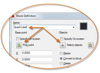
2. Choose Home tab,  Block panel, Create to start the BLOCK command. The Block Definition dialog box opens.


3. Type a name in the Name text box. The name can have spaces.


4. You need to specify a base point. That’s the point at which you’ll insert the block. In the Base Point section, click Pick Point. Be sure to use an object snap for accuracy! You’ll immediately be returned to the dialog box.


5. In the Objects section, click the Select Objects button. Select the objects and press Enter to return to the dialog box. Tip: You can select the objects before using the command and they’ll show up in the dialog box.


6. Just below, choose Retain, Convert to Block, or Delete. These options control what happens after you create the block.


7. In the Behavior section, you can make a block Annotative (more info here), force it to scale uniformly and choose whether to allow exploding.


8. In the Settings area, choose the block unit. You can choose Unitless but if you choose a unit, AutoCAD will try to scale the block appropriately when you insert it into another drawing. You can also add a hyperlink if you want.


9. Finally, you can add a description in the Description box. A description is helpful in the Design Center, when you want to insert the block from another drawing.


10. Click OK to complete the box. If you chose Delete, the objects disappear. You can use the OOPS command to bring them back.


10.20.2012

Cad Tip Of The Day


How to Maintain the Attributes Value when Exploding

Block attributes is a nice tool to have. We can use it to preserve text style and size as annotation block. Drawing title and title block is a good example. The problem is when we need it explode it somehow, we will loose any information we put in the attribute.


To preserve the values, do not use explode. Use BURST instead.

10.07.2012

Find Commands by Tabbing


Engineering Technician Hayden Clarke sent a tip that helps users of AutoCAD and its verticals to find commands quickly through keyboard entry.

"I recently discovered tabbing to find that command that you've been thinking about, but can’t quite remember. Quite often, you may remember the first couple of letters for a command but cannot remember the rest for the life of you. The trick is to type the first few letters you know, then press the Tab button. This will cycle through all the commands beginning with the letters you inputted. When you find the one you're looking for, simply press Enter.

"For example, if I type REG in the Command line and start pushing Tab, the following will appear: REG…REGEN…REGEN3…REGENALL…REGENAUTO…REGENMODE…REGION…etc. It makes remembering commands that much easier — but only if you remember this one."


8.19.2012

CAD Tip Of The Day

Retain block attribute values when exploding them


block-attributes

Block attributes  are a very useful tool to have. The problem is when you explode a block we somehow lose the data values associated with that attribute. In order to preserve the attribute value, use the command 'BURST' instead of the 'EXPLODE' command.


Cad Tip of the Day

5 Reasons for Slow Opening of Files

1. Full of Xref say 5 to 10 times. Better purge and audit to lessen the file size. If it’s still big, save as the DWG file to DXF format. Open the Dxf file, purge and audit then save as to DWG file.

2. Many blocks within the drawings especially repeated. Better use the command "Group" for repetition of objects.

3. New added font is not in the default of AutoCAD.

4. Overlaid lines with the same color in one location. Use "Overkill" command. Overkill removes duplicate geometry as well as overlapping lines, arcs, and polylines. Also, combines partially overlapping or contiguous ones.

5. A file contains too much or excess scale. This problem limited to AutoCAD 2008 and 2009 version. Solution: Download Scale List Cleanup Utility. This utility repairs a problem with files that contain excess scales.

BIM: What's It All About? A Beginner-to-Advanced Guide to Building Information Modeling

The construction industry is evolving faster than ever, and at the center of this transformation is BIM (Building Information Modeling) . Wh...